

As P3 Series Digital Strain Indicator Operating Instructions
Accepts only Domestic inquiries
Get LatestPrice
AS P3 Series Digital Strain Indicator Operating Instructions DIGITAL STRAIN INDICATOR INSTRUCTION MANUAL FOR AS-P3 Series 1.0 INTRODUCTION Ajay Sen...View Product Details
Product Overview
Key Features
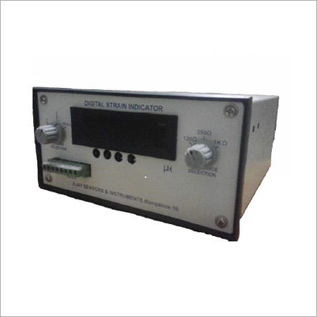
AS P3 Series Digital Strain Indicator Operating Instructions DIGITAL STRAIN INDICATOR INSTRUCTION MANUAL FOR AS-P3 Series 1.0 INTRODUCTION Ajay Sensors Model: AS-P3 Series is a single channel micro controller based, versatile process indicator instrument. This precision instrument is ideally suited for industrial and laboratory applications. The instrument is designed to use with resistive strain gauges and strain-gauge based transducers. This manual contains the information about AS-P3 Series. Please go through this manual carefully before operating the instrument.2.0 Features Built in precision bridge completion for 120, 350 and 1000 half and quarter bridges Press to tare / zero Analog output (Optional) Serial communication (Optional) 3.0 SPECIFICATIONS 3.1 Input ConnectionsFront Panel screw type Quantity: 8 NumbersWire size: 16 to 28 AWG 3.2 Bridge ConfigurationsTypes: Quarter, Half and Full BridgesInternal Bridge Completion:Quarter Bridge: 120, 350 and 1000 0.05%Half Bridge: 120, 350 and 1000 0.05% 3.3 Display6 digits, seven segment LED display (12.5mm height, red) 3.4 Measurement Range / ResolutionStrain Range: 10,000 at Gauge Factor (GF) = 2.000 ( 5 mV/V)Resolution: 1 at Gauge Factor (GF) = 2.000 ( 0.0005 mV/V)Update Rate : 8 samples / sec 3.5: Measurement Accuracy: 0.2% of reading 5 counts 3.6: Gauge Factor ControlRange: 0.5000 to 9.900 3.7 Balance controlFront panel Tare switch 3.8 Bridge Excitation2.0 VDC nominal 3.9 Communication interfaceRS 232 C 3.10 Shunt CalibrationLocation: Across bridge completion resistorsValues:P- to D120: 11.94 K 0.1% ( 5000 at GF = 2.000)P- to D350: 34.8 K 0.1% ( 5000 at GF = 2.000)P- to D1K: 99.5 K 0.1% ( 5000 at GF = 2.000) 3.11 Analog OutputValue: 0 to 10 VDCRange: 0 to 5000 Output load resistance: 2 KConnector: BNC 3.12 Power230 V AC Mains Operation, 50 Hz 3.13 Operational EnvironmentTemperature: 0 to 50CHumidity: Upto 90% Rh, non condensing 3.14 Enclosure184 x 96 x 200mm DIN enclosure 3.15 Weight1.0 Kg Settable Parameters:Gauge Factor Front Panel Keys; Menu; To scroll through the menus.Inc; Increments the blinking menu parameter, To reset the peak and to tare the reading.Shift; Shifts the blinking menu digit.Enter; Stores configuration and Toggles between peak & Normal mode. 3.0 Keyboard Description: The front panel of the instrument consists of 4 keys whose description is given below: 3.1 MENU: Pressing the menu key repeatedly enables the user to scroll through the different menus available in the instrument. 3.2 INC: INC or Increment key is used increment the value of the blinking digit in menu. In the normal mode, when not in menu, this key is used for resetting the Peak value and if it is pressed for more than 15 sec. it will tare the reading. 3.3 SHIFT: SHIFT key is used to shift the blinking digit. 3.4 ENTER: When the menu is STOR, ENTER key is used to store the menu settings in the non volatile memory. In the normal mode, when not in menu, this key is used to switch between normal display and peak display. 4.0 Description of menus 4.1 Gauge Factor Control (b xxxx); where x is one of 1, 2, 3 or 4 (1 refers to 1st key or the MENU key 2 refers to 2nd key or the INC key 3 refers to the 3rd key or the SHIFT key and 4 refers to the ENTER key. 4.24 Saving the menu settings (stor): This menu is used to store all the settings in the non volatile memory band it will be loaded while powering up. Press ENTER key to save the changes made in the menus. When ENTER is pressed, the display will blink once to indicate that the setting have been stored. 5.0 Accessing the hidden (or Masked) Menus : The Menus which are hidden may have to be accessed for re-setting or for any other purpose. The procedure to access all menus (irrespective of masking is as follows) Put the instrument OFF and put it ON, while holding the SHIFT key down.Release the SHIFT key after the display appears. The display will now show the message P xx, where xx starts counting from 00 to 20.Input the pass word (as set in Menu P 1234).If a wrong pass Word is entered or a pass word is not entered before the count reaches 20, the display will show FAIL and goes back to normal modewithout enabling all the Menus.If a correct Pass Word is entered, then the display will show PASS and goes to normal mode after enabling all the Menus.Now one can go through all the Menus by pressing Menu key. 6.0 Peak, Valley and Tare functions; In the normal mode, (i.e., When not in Menu mode ) pressing Enter key will toggle the display between normal value the PEAK (Max) value and the Valley (Min) value. When PEAK is displayed a P will be displayed in front of the value. And when Valley is displayed, u will be displayed in front of the value. Since sign is displayed in the same digit as P and u the middle segment of P will disappear for + value and for negative values u will look like o. Pressing INC key will reset the PEAK. To tare the value, press INC key continuously for 5 sec. 7.0 Front Panel Input: Screw TerminalsBridge Selection switchResistance Selection switchMenu keys for setting 8.0 Strain gauges and strain gauge based transducers are connected to AS-P3 through the front panel input terminals. Connections can be made whether the unit if on or off. But we recommend to power off the unit and do the connections. Quarter Bridge Connections The following configuration illustrates the connections for making a three wire quarter bridge connection. Select the dummy terminal (D120, D350 or D1K) to correspond with the nominal resistance of the strain gage. Ensure Bridge Selection switch to be selected is 1/4 (Quarter) Ensure Resistance Selection switch is selected according to the connections Half Bridge Connections The following configuration illustrates the connections for making a three wire half bridge connection. Ensure Bridge Selection switch to be selected is 1/2 (Half) Ensure Resistance Selection switch is selected according to the connections Full Bridge / Transducers Connections The following configuration illustrates the connections for making a full bridge connection. Ensure Bridge Selection switch to be selected is Full Ensure Resistance Selection switch is selected according to the connections.
Company Details
AJAY SENSORS & INSTRUMENTS, Established in 1993 at Bengaluru in Karnataka, is a leading Exporter,Manufacturer,Supplier of Electronic Liquid Level Controllers & Indicators in India. AJAY SENSORS & INSTRUMENTS is one of Trade India's verified and trusted sellers of listed products. With extensive experience in supplying and trading AS P3 Series Digital Strain Indicator Operating Instructions, AJAY SENSORS & INSTRUMENTS has made a reputed name for itself in the market with high-quality AS P3 Series Digital Strain Indicator Operating Instructions, AST5100 Low Differential Pressure Transmitter, Digital Indicator, etc.
Focusing on a customer-centric approach, AJAY SENSORS & INSTRUMENTS has a pan-India presence and caters to a huge consumer base throughout the country. Buy Electronic Liquid Level Controllers & Indicators in bulk from AJAY SENSORS & INSTRUMENTS at Trade India quality-assured products.
Focusing on a customer-centric approach, AJAY SENSORS & INSTRUMENTS has a pan-India presence and caters to a huge consumer base throughout the country. Buy Electronic Liquid Level Controllers & Indicators in bulk from AJAY SENSORS & INSTRUMENTS at Trade India quality-assured products.
Business Type
Exporter, Manufacturer, Supplier
Employee Count
8
Establishment
1993
GST NO
29AAGFA6226N1Z3
Certification
ISO 9002
Seller Details
A
AJAY SENSORS & INSTRUMENTS
GST
29AAGFA6226N1Z3
Partner
Mr. Ajay Kumar M. V.
AddressView on Map
45/17, 12 'A' Cross, Gubbanna Industrial Garden, 6th Block, Rajajinagar, Bengaluru, Karnataka, 560010, India
Report incorrect details
Related Products
Load Indicator - Application: Automatic Weighing
Price - 82.66 USD ($) (Approx.)
MOQ - 1 Piece/Pieces
HARIOM ELECTRONICS
Vadodara, Gujarat
Digital Load Indicator For Load Cells Accuracy: 0.1 %
MOQ - 1 Piece/Pieces
ADI ARTECH TRANSDUCERS PVT. LTD.
Vadodara, Gujarat
White Digital Load Indicators
Price - 20000 INR (Approx.)
MOQ - 1 null
PARAMETRIC RESEARCH & CONTROL
Gurugram, Haryana
More Products From This Seller
Explore Related Categories
- Tradeindia
- Electronic Liquid Level Controllers & Indicators
- Digital Load Indicator
- As P3 Series Digital Strain Indicator Operating Instructions In Gubanna Indl Estate/area (Rajajinagar)